Overview
This document is a reference to the file format used in pbrt-v4, the version of the system corresponding to the forthcoming fourth edition of Physically Based Rendering; it serves as a comprehensive reference. The pbrt-v4 User's Guide documents how to use pbrt with more focus on how to achieve various tasks.
The scene description files used by pbrt are plain text files. The file format was designed so that it would be both easy to parse and easy for applications to generate from their own internal representations of scenes. However, pbrt supports a variety of efficient binary encodings for scene data such as PLY files for meshes and various image formats for textures; thus, the size of the text input files is often not too large.
A pbrt scene file consists of a series of statements; different statements specify the geometry and light sources in the scene and set overall rendering parameters (such as which light transport algorithm to use or the image resolution). Each statement in these files corresponds directly to a pbrt API method defined in the ParserTarget class in pbrt-v4. (See also Appendix C in the fourth edition of the Physically Based Rendering book.) For example, when the WorldBegin statement appears in the input, an implementation of the ParserTarget::WorldBegin() method is called.
Differences from pbrt-v3
We have tried to minimize changes to the file format in order to make it as easy as possible to use existing scene description files with pbrt-v4. However, a number of changes were necessary for new functionality or changes in the system's implementation.
To make it easier to bring pbrt-v3 scenes to pbrt-v4, pbrt now provides an --upgrade command-line option:
$ pbrt --upgrade scene.pbrt > scene-v4.pbrt
In some cases, it may not be possible to upgrade pbrt-v3 scenes automatically; pbrt will then issue an error indicating which part of the scene description requires manual attention.
Major changes to the scene description include:
- Environment maps used for image-based lighting should now use Clarberg's equal-area mapping. pbrt's imgtool utility provides a makeequiarea operation that converts equirectangular environment maps (as used in pbrt-v3) to this parameterization.
- The WorldEnd directive has been removed. WorldBegin is still used to separate rendering options from the scene specification but rendering then begins when the end of the input files is reached. This change means that multiple images can no longer be rendered from a single invocation of pbrt, though that feature was both rarely used and buggy.
- The TransformBegin and TransformEnd directives have also been removed. AttributeBegin and AttributeEnd should be used instead. (In pbrt, they have nearly the same semantics.)
- The parser has become more strict about types in parameter lists. For example, "point P" will now give an error; "point3 P" must be used instead. (Previously, both were allowed.)
- The set of materials provided by pbrt is nearly all new and better reflects modes of physical scattering at surfaces. (Thus, for example, materials like "mirror" and "plastic" are no longer available, having been replaced with "conductor" and "coateddiffuse", which provide functionality that is a superset of those.)
- Various parameter names have been changed to improve clarity or consistency. (For example, the xwidth parameter to various pixel reconstruction filters is now named xradius.) Refer to the the pbrt-v4 File Format documentation for further details.
- The rarely-used and occasionally-buggy "cone", "hyperboloid", and "paraboloid" Shapes have been removed.
- The "image" Film is gone; use "rgb" instead.
- The "fourier" material is no longer supported and has been replaced with "measured", which is based on a parameterization that better matches measured BRDF data.
Example of a pbrt file
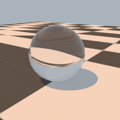
Here is a short example of a pbrt input file: Between the start of the file and the WorldBegin statement, overall options for rendering the scene are specified, including the camera type and position, the sampler definition, and information about the image to be generated. After WorldBegin, the lights, geometry, and scattering volumes (if any) in the scene are defined.
LookAt 3 4 1.5  # eye
       .5 .5 0  # look at point
       0 0 1    # up vector
Camera "perspective" "float fov" 45

Sampler "halton" "integer pixelsamples" 128
Integrator "volpath"
Film "rgb" "string filename" "simple.png"
     "integer xresolution" [400] "integer yresolution" [400]

WorldBegin

# uniform blue-ish illumination from all directions
LightSource "infinite" "rgb L" [ .4 .45 .5 ]

# approximate the sun
LightSource "distant"  "point3 from" [ -30 40  100 ]
   "blackbody L" 3000 "float scale" 1.5

AttributeBegin
  Material "dielectric"
  Shape "sphere" "float radius" 1
AttributeEnd

AttributeBegin
  Texture "checks" "spectrum" "checkerboard"
          "float uscale" [16] "float vscale" [16]
          "rgb tex1" [.1 .1 .1] "rgb tex2" [.8 .8 .8]
  Material "diffuse" "texture reflectance" "checks"
  Translate 0 0 -1
  Shape "bilinearmesh"
      "point3 P" [ -20 -20 0   20 -20 0   -20 20 0   20 20 0 ]
      "point2 uv" [ 0 0   1 0    1 1   0 1 ]
AttributeEnd
When this input file is rendered with pbrt-v4, this image is generated:
General structure of a pbrt input file
A scene description file starts with a series of directives that describe the camera, film, and sampling and light transport algorithms to use in rendering the scene. These are followed by the WorldBegin directive; after WorldBegin, the world definition block starts, and it is no longer legal to specify different definitions of any of the objects defined in the initial section of the file. However, lights, materials, textures, and shapes, can be defined inside the world block (and can only be defined inside the world block). Participating media can be specified before or after WorldBegin, as it can be associated with cameras, lights, and shapes.
The following section, Scene-wide rendering options, documents the directives that are valid outside of the world definition block. The subsequent section, Describing the scene, documents the directives for defining the shapes, materials, lights, etc., that define the scene.
When there is nothing left to parse, rendering begins. At this point, the Integrator defined takes control and performs the required rendering computation.
The hash character # denotes that the rest of the line is a comment and should be ignored by the parser.
Some of the statements in the input file, such as WorldBegin, AttributeEnd, and so on, have no additional arguments. Others, such as those related to specifying transformations, such as Rotate and LookAt, take a predetermined number of arguments of predetermined type. (For example, Translate is followed by three floating-point values that give the x, y, and z components of the translation vector.) The remainder of the statements take a variable number of arguments and are of the form:
identifier "type" parameter-list
For example, the Shape identifier describes a shape to be added to the scene, where the type of shape to create is given by a string (e.g., "sphere") and is followed a list of shape-specific parameters that define the shape. For example,
Shape "sphere" "float radius" [5]
defines a sphere of radius 5. (See Shapes for documentation of the parameters taken by the various shapes implemented in pbrt.)
For these statements, the "type" string gives the name of the particular shape, light., etc., and parameter-list gives the parameters to pass to the implementation. With this design, pbrt's parser doesn't need to know anything about the semantics of the parameters; it just needs to know how to parse parameter lists and store the parameter names and values that it finds in a structure for later processing.
Parameter Lists
Variable-length lists of named parameters and their values are the key meeting ground between the parsing system and the objects that are created to represent the scene. Each of these lists holds an arbitrary number of name/value pairs, with the name in quotation marks and the value or values in square brackets:
"type name" [ value or values ]
If there is only a single value, the brackets are optional. For example,
"float fov" 30
specifies a parameter "fov" that is a single floating-point value, with value 30.
Alternatively,
"float cropwindow" [0 .5 0 .25]
specifies that "cropwindow" is a floating-point array with the given four values.
The type of each parameter must always be given along with its name; pbrt has no built-in knowledge of any parameter names. This simplifies the parsing system, although it does create a small burden for the creator of the input file.
pbrt supports eleven parameter types: integer, float, point2, vector2, point3, vector3, normal3, spectrum, rgb, blackbody, bool, and string.
The point2 and vector2 types take two floating-point values to specify each value (and similarly for their 3D equivalents). string parameters must be inside quotation marks, and bool parameters are set with the values true and false.
"string filename" "foo.exr"
"point3 origin" [ 0 1 2 ]
"normal N" [ 0 1 0  0 0 1 ] # array of 2 normals
"bool renderquickly" true
Colors and Spectra
pbrt provides three different ways of specifying spectral values in scene description files. RGB values are commonly used, though see the discussion in Section 5.2.2 on page 325 of the third edition of "Physically Based Rendering" for discussion of the shortcomings of this representation. RGB color values can be specified with the rgb type. (They are interpreted as being with respect to the current RGB color space, which can be specified using the ColorSpace directive, which is described below):
"rgb reflectance" [ .2 .5 .3 ]
specifies the RGB color with red equal to 0.2 and so forth.
Alternatively, a normalized blackbody spectral distribution with maximum value of 1 can be specified using blackbody.
"blackbody emission" 6500
General spectral distributions can be specified with a series of (wavelength, value) pairs, where wavelengths are specified in nm:
"spectrum reflectance" [ 300 .3 400 .6 410 .65 415 .8 500 .2 600 .1 ]
specifies a piecewise-linear SPD with a value of 0.3 at 300nm, 0.6 and 400nm, and so forth. Since complex sampled SPDs may have many values, they can also be provided using a file on disk:
"spectrum reflectance" "filename"
Where the filename specifies the path to a plain text file with pairs of floating-point (wavelength, value) as above. The parser for these files allows uses # to denote a comment that goes to the end of the current line.
A number of useful spectral distributions are also built in to pbrt; if the following names are provided as string values to spectrum parameters, the corresponding spectral distribution is used:
| String | Description |
|---|---|
| "glass-BK7" | Index of refraction for BK7 glass |
| "glass-BAF10" | Index of refraction for BAF10 glass |
| "glass-FK51A" | Index of refraction for FK51A glass |
| "glass-LASF9" | Index of refraction for LASF9 glass |
| "glass-F5" | Index of refraction for F5 glass |
| "glass-F10" | Index of refraction for F10 glass |
| "glass-F11" | Index of refraction for F11 glass |
| "metal-Ag-eta" / "metal-Ag-k" | Index of refraction and extinction coefficient for silver. |
| "metal-Al-eta" / "metal-Al-k" | Index of refraction and extinction coefficient for aluminum. |
| "metal-Au-eta" / "metal-Au-k" | Index of refraction and extinction coefficient for gold. |
| "metal-Cu-eta" / "metal-Cu-k" | Index of refraction and extinction coefficient for copper. |
| "metal-CuZn-eta" / "metal-CuZn-k" | Index of refraction and extinction coefficient for copper zinc alloy. |
| "metal-MgO-eta" / "metal-MgO-k" | Index of refraction and extinction coefficient for magnesium oxide. |
| "metal-TiO2-eta" / "metal-TI02-k" | Index of refraction and extinction coefficient for titanium dioxide. |
| "stdillum-A" | CIE standard illuminant A. |
| "stdillum-D50" | CIE standard illuminant D50. |
| "stdillum-D65" | CIE standard illuminant D65. |
| "stdillum-F1" – "stdillum-F12" | CIE standard illuminants F1 through F12. |
| "illum-acesD60" | D60 illuminant from ACES. |
Transformations
A series of directives modify the current transformation matrix (CTM). When the scene's camera is specified with a Camera directive, the CTM defines the transformation from world space to camera space; when a light or shape is created, the CTM specifies the transformation from object space to world space.
When parsing begins, the CTM is the identity transformation; furthermore, it is is reset to the identity when the WorldBegin directive is encountered. The following directives modify the CTM:
| Input File Syntax |
|---|
| Identity |
| Translate x y z |
| Scale x y z |
| Rotate angle x y z |
| LookAt eye_x eye_y eye_z look_x look_y look_z up_x up_y up_z |
| CoordinateSystem "name" |
| CoordSysTransform "name" |
| Transform m00 ... m33 |
| ConcatTransform m00 .. m33 |
For example, Translate takes three floating-point values, x, y, and z, and cause the CTM to be set it to its product of with the matrix representing the given translation. An arbitrary transformation to multiply the CTM with can be specified using ConcatTransform; alternatively, Transform resets the CTM to the specified matrix.
A name can be associated with the CTM using the CoordinateSystem directive. In turn, the CTM can later be reset to the recorded transformation using CoordSysTransform. pbrt automatically records the camera transformation matrix in the "camera" named coordinate system; this can be useful for placing light sources with respect to the camera, for example.
pbrt supports animated transformations by allowing two transformation matrices to be specified at different times. The TransformTimes directive, which must be outside of the world definition block, defines these two times with floating-point values:
TransformTimes start end
Then, the ActiveTransform directive indicates whether subsequent directives that modify the CTM should apply to the transformation at the starting time, the transformation at the ending time, or both. The default is that both matrices should be updated:
Translate 1 0 0  # applies to both, by default
ActiveTransform StartTime
Rotate 90 1 0 0
ActiveTransform EndTime
Rotate 120 0 1 0
ActiveTransform All
Including Files
Two statements make it possible to specify other files to be parsed. The first of them is Include, which behaves similarly to the #include directive in C++: parsing of the current file is suspended, the specified file is parsed in its entirety, and only then does parsing of the current file resume. Its effect is equivalent to direct text substitution of the included file.
Include "geometry/car.pbrt"
Included files may be compressed using gzip. If a scene file name has a ".gz" suffix, then pbrt will automatically decompress it as it is read from disk.
Include "geometry/bigcar.pbrt.gz"
The Import directive can also be used to specify a file to be parsed. It is similar to Include in that it takes a single filename argument and that the file may be gzip-compressed, but its semantics are that the definitions of any named objects—object instances, named textures, named materials, or named participating media—may not be referenced in the initial file with the Import statement. Thus, Import does not correspond to direct text substitution. In return for this restriction, it is possible to parse imported files in parallel; judicious use of Import can thus significantly improve pbrt's startup time when rendering complex scenes.
Import "geometry/complex-car.pbrt"
If the filename given to a Include or Import statement is not an absolute path, its path is interpreted as being relative to the directory of the initial file being parsed as specified with pbrt's command-line arguments.
Scene-wide rendering options
This section describes rendering options that must be specified before the WorldBegin statement.
General Options
A number of general options that control rendering can be specified using the Option directive. Many of these can also be specified via command-line arguments.
Option "type name" valueThe following options can be specified:
| Type | Name | Default Value | Description |
|---|---|---|---|
| bool | disablepixeljitter | false | Forces all pixel samples to be through the center of the pixel area. Enabling this can be useful when computing reference images and then computing error with respect to them in that it eliminates differences due to geometric sampling that may not be of interest. |
| bool | disabletexturefiltering | false | Forces point sampling at the finest MIP level for all texture lookups. (Rarely useful.) |
| bool | disablewavelengthjitter | false | Forces all samples within each pixel to sample the same wavelengths. RGB images will generally have objectionable color error but this can also be useful when computing error with respect to reference images when error due to random wavelength sampling shouldn't be included. |
| float | displacementedgescale | 1 | Global scale factor applied to triangle edge lengths before evaluating the edge length test for refinement when applying displacement mapping. Increasing this value will generally reduce memory use and startup time when rendering scenes with displacement mapping. |
| string | msereferenceimage | (none) | Specifies the filename of an image to use when computing mean squared error versus the number of pixel samples taken (see "msereferenceout" below). |
| string | msereferenceout | (none) | Filename for per-sample mean squared error results. When both this and "msereferenceimage" are specified, the mean squared error of the current image and the reference image is computed after each sample is taken and the results are stored in text format in this file. |
| string | rendercoordsys | "cameraworld" | Specifies the coordinate system to use for rendering computation. The default, "cameraworld" translates the scene so that the camera is at the origin. "camera" uses camera space (performance may suffer due to the scene being rotated) and "world" uses world space (accuracy may suffer due to floating-point precision). |
| integer | seed | 0 | Seed to use for pseudo-random number generation during rendering. Rendering a scene with different seed values will give independent results, which can be useful for statistical analysis. |
| bool | forcediffuse | false | Force all materials to be diffuse. (Note: not currently supported with the --wavefront and --gpu integrators.) |
| bool | pixelstats | false | Write out images after rendering that encode per-pixel statistics including time spent rendering each pixel and any other per-pixel statistics added using STAT_PIXEL_COUNTER or STAT_PIXEL_RATIO in the pbrt source code. |
| bool | wavefront | false | Enables the "wavefront" integrator (i.e., the integrator used for GPU rendering, but running on the CPU.) |
Cameras
The Camera directive specifies the camera used for viewing the scene.
The default camera is a PerspectiveCamera with a 90 degree field of view:
Camera "perspective" "float fov" [90]
When the Camera directive is encountered in an input file, the current transformation matrix is used to initialize the camera-from-world transformation.
pbrt provides four camera implementations:
| Name | Implementation Class |
|---|---|
| "orthographic" | OrthographicCamera |
| "perspective" | PerspectiveCamera |
| "realistic" | RealisticCamera |
| "spherical" | SphericalCamera |
Two parameters that set the camera's shutter open times are common to all cameras in pbrt.
| Type | Name | Default Value | Description |
|---|---|---|---|
| float | shutteropen | 0 | The time at which the virtual camera shutter opens. |
| float | shutterclose | 1 | The time at which the virtual camera shutter closes. |
The PerspectiveCamera and OrthographicCamera share two additional parameters that describe the imaging area:
| Type | Name | Default Value | Description |
|---|---|---|---|
| float | frameaspectratio | (see description) | The aspect ratio of the film. By default, this is computed from the x and y resolutions of the film, but it can be overridden if desired. |
| float | screenwindow | (see description) | The bounds of the film plane in screen space. By default, this is [-1,1] along the shorter image axis and is set proportionally along the longer axis. |
PerspectiveCamera and OrthographicCamera also support images that include defocus blur due to finite camera apertures. Both use the following two parameters to set parameters related to lens focus.
| Type | Name | Default Value | Description |
|---|---|---|---|
| float | lensradius | 0 | The radius of the lens. The default value yields a pinhole camera. |
| float | focaldistance | 10^30 | The focal distance of the lens. If "lensradius" is zero, this has no effect. Otherwise, it specifies the distance from the camera origin to the focal plane. |
The perspective camera has a parameter for setting the camera's field of view.
| Type | Name | Default Value | Description |
|---|---|---|---|
| float | fov | 90 | Specifies the field of view for the perspective camera. This is the spread angle of the viewing frustum along the narrower of the image's width and height. |
The SphericalCamera captures light arriving at the camera from all directions. It takes a parameter that describes the mapping to use from directions to 2D points on the image.
| Type | Name | Default Value | Description |
|---|---|---|---|
| string | mapping | "equalarea" | By default, an area-preserving mapping based on an octahedral encoding of the unit sphere is used. Alternatively, an equirectangular mapping can be specified using "equirectangular". |
The RealisticCamera simulates imaging from light rays passing through complex lens systems. It takes a number of additional parameters.
| Type | Name | Default Value | Description |
|---|---|---|---|
| string | lensfile | "" | Specifies the name of a lens description file that gives the collection of lens elements in the lens system. A number of such lenses are available in the lenses directory in the pbrt-v4 scenes distribution. |
| float | aperturediameter | 1.0 | Diameter of the lens system's aperture, specified in mm. The smaller the aperture, the less light reaches the film plane, but the greater the range of distances that are in focus. |
| float | focusdistance | 10.0 | Distance in meters at which the lens system is focused. |
| string | aperture | (unspecified) | Allows specifying the shape of the camera aperture, which is circular by default. The values of "gaussian", "square", "pentagon", and "star" are associated with built-in aperture shapes; other values are interpreted as filenames specifying an image to be used to specify the shape. |
Samplers
The Sampler generates samples for the image, time, lens, and Monte Carlo integration. A number of implementations are provided; the default "zsobol"—is an instance of the ZSobolSampler that takes 16 samples per pixel.
| Name | Implementation Class |
|---|---|
| "halton" | HaltonSampler |
| "independent" | IndependentSampler |
| "paddedsobol" | PaddedSobolSampler |
| "sobol" | SobolSampler |
| "stratified" | StratifiedSampler |
| "zsobol" | ZSobolSampler |
Note that the IndependentSampler is the least effective of the samplers and is mostly included only for comparison with more sophisticated approaches.
For samplers that use pseudorandom values (either directly when jittering sample positions or for scrambling), a seed for the pseudorandom number generator can be specified. Specifying different seeds makes it possible to do independent runs of pbrt, which can be useful for analysis of convergence or error of various sampling algorithms.
| Type | Name | Default Value | Description |
|---|---|---|---|
| integer | seed | (See description) | A seed to use for the pseudorandom number generator. The default seed value is zero, though the --seed command-line argument can be used to specify a different seed. If a seed is specified in the scene description file, it overrides a value specified on the command-line. |
All of the samplers other than the StratifiedSampler take a "pixelsamples" parameter that sets the number of samples to take in each pixel area. For PaddedSobolSampler, SobolSampler, and ZSobolSampler, this value must be a power of two. For those, if a non-power-of-two value is provided, it is rounded up to the next power of two.
| Type | Name | Default Value | Description |
|---|---|---|---|
| integer | pixelsamples | 16 | The number of samples to take in each pixel. |
The four Samplers that are based on low-discrepancy sample points (HaltonSampler, PaddedSobolSampler, SobolSampler, and ZSobolSampler) provide an option that chooses among algorithms that randomize the sample points while still preserving their low-discrepancy properties.
| Type | Name | Default Value | Description |
|---|---|---|---|
| string | randomization | "fastowen" ("permutedigits" for the HaltonSampler). | Specifies a randomization algorithm to use. "none" disables randomization; "permutedigits" applies a random permutation to the digits of the sample; "owen" applies Owen scrambling; "fastowen" (not available with the the HaltonSampler) applies an efficient approximation to Owen scrambling. |
The StratifiedSampler takes separate specifications of the number of pixel samples in each of the two dimensions and also provides control of whether samples are jittered.
| Type | Name | Default Value | Description |
|---|---|---|---|
| bool | jitter | true | Whether or not the generated samples should be jittered inside each stratum; this is generally only worth setting to "false" for comparisons between jittered and uniform sampling—uniform sampling will almost always give a worse result. |
| integer | xsamples | 4 | The number of samples per pixel to take in the x direction. |
| integer | ysamples | 4 | The number of samples per pixel to take in the y direction. In general, "xsamples" and "ysamples" should be set to the same value for best results. |
Color Spaces
RGB colors specified in the scene description are interpreted with respect to the current color space when the RGB value is encountered. (For images used as texture maps, the current color space is not used; RGB images are interpreted as being sRGB unless they are stored in an image format like OpenEXR that allows encoding the color space and another color space is specified in the image's metadata.)
The ColorSpace directive specifies the current color space.
ColorSpace "rec2020"
Four color spaces are currently available. sRGB is the default.
| Name | Description |
|---|---|
| aces2065-1 | The standard color space defined in the Academy Color Encoding System. |
| rec2020 | The ITU-R Recommendation BT.2020 color space. |
| dci-p3 | The DCI-P3 color space, widely used in current displays. |
| srgb | The venerable sRGB color space; it has the smallest gamut of pbrt-v4's color spaces, but is still widely used. |
Film
The Film directive specifies the characteristics of the image being generated by the renderer. Three Film implementations are available:
- "rgb", corresponding to RGBFilm: the default film if none is specified; stores RGB images using the current color space when the Film directive is encountered.
- "gbuffer", corresponding to GBufferFilm: in addition to RGB, stores multiple additional channels that encode information about the visible geometry in each pixel. Images must be written in OpenEXR format with this film. The User's Guide has further documentation about the format of the information stored by this film implementation.
- "spectral", corresponding toSpectralFilm: stores a discretized spectral distribution at each pixel, in addition to RGB (for convenience when viewing images.) Images must be written in OpenEXR format with this film. Spectral data is stored using the format described by Fichet et al..
A number of parameters common to all Film implementations specify the resolution of the image, an optional subset of it to be rendered, and how to save it when it is complete:
| Type | Name | Default Value | Description |
|---|---|---|---|
| integer | xresolution | 1280 | The number of pixels in the x direction. |
| integer | yresolution | 720 | The number of pixels in the y direction. |
| float[4] | cropwindow | [ 0 1 0 1 ] | The sub-region of the image to render. The four values specified should be fractions in the range [0,1], and they represent x_min, x_max, y_min, and y_max, respectively. These values are in normalized device coordinates, with (0,0) in the upper-left corner of the image. |
| integer[4] | pixelbounds | [ 0 xres 0 yres ] | A sub-region of the image to render, specified using pixel coordinates. |
| float | diagonal | 35 | Diagonal length of the film, in mm. (This value is only used when the RealisticCamera is used.) |
| string | filename | "pbrt.exr" | The output filename. |
| bool | savefp16 | true | Whether 16-bit floating point values (as opposed to 32-bit floating point values) should be used when saving images in OpenEXR format. |
All Film implementations also take a number of parameters that affect how the image is recorded:
| Type | Name | Default Value | Description |
|---|---|---|---|
| float | iso | 100 | Film sensitivity to light; final pixel values are scaled by the "iso" value divided by 100. |
| float | whitebalance | 0 | If non-zero, this gives a temperature in degrees kelvin that is used as the reference color temperature used for whitebalancing. |
| string | sensor | "cie1931" | Characterizes the sensor's response for red, green, and blue colors. The default corresponds to using the CIE 1931 spectral response curves. Alternatively, the measured response curves are available for the following cameras: "canon_eos_100d", "canon_eos_1dx_mkii", "canon_eos_200d", "canon_eos_200d_mkii", "canon_eos_5d", "canon_eos_5d_mkii", "canon_eos_5d_mkiii", "canon_eos_5d_mkiv", "canon_eos_5ds", "canon_eos_m", "hasselblad_l1d_20c", "nikon_d810", "nikon_d850", "sony_ilce_6400", "sony_ilce_7m3", "sony_ilce_7rm3", and "sony_ilce_9". |
| float | maxcomponentvalue | infinite | Image sample values with luminance greater than this value are clamped to have this luminance. (This is a hack, but can be useful for eliminating large variance spikes in scenes with difficult light transport.) |
The GBufferFilm takes a parameter that specifies the coordinate system that per-pixel geometric data (positions, normals, etc.) is stored in:
| Type | Name | Default Value | Description |
|---|---|---|---|
| string | coordinatesystem | "camera" | Geometric data is stored in camera space by default. Alternatively, "world" can be specified for world space. |
Finally, the SpectralFilm takes a number of parameters that control how spectra are stored at each pixel:
| Type | Name | Default Value | Description |
|---|---|---|---|
| integer | nbuckets | 16 | Number of buckets that the spectral range is discretized into. |
| float | lambdamin | 360 | Minimum wavelength for spectral range. |
| float | lambdamax | 830 | Maximum wavelength for spectral range. |
The RGBFilm uses the suffix of the given output filename to determine the image file format to use. pbrt supports PFM and OpenEXR for storing images with pixel values stored directly as floating-point values; QOI and PNG can also be used, though these only provide 8 bits per color channel of precision.
Both GBufferFilm and SpectralFilm require that the OpenEXR format be used for output, as it provides capabilities that both of them require for storing multi-channel images with arbitrary semantics.
Filters
The Film implementations use an instance of the Filter class to filter sample values to compute final pixel values. The filter is specified with the PixelFilter directive. pbrt provides a number of filter implementations, listed below along with the respective default filter radii. The default filter is "gaussian".
| Name | Implementation Class | Default Radius |
|---|---|---|
| "box" | BoxFilter | 0.5 |
| "gaussian" | GaussianFilter | 1.5 |
| "mitchell" | MitchellFilter | 2 |
| "sinc" | LanczosSincFilter | 4 |
| "triangle" | TriangleFilter | 2 |
All filter implementations take two parameters for manually setting the filter radius. The default values for these parameters vary according to which filter is used, as listed in the table above.
| Type | Name | Description |
|---|---|---|
| float | xradius | The width of the filter in the x direction. |
| float | yradius | The width of the filter in the y direction. |
The "gaussian" filter takes an additional parameter that adjusts the rate of Gaussian falloff.
| Type | Name | Default Value | Description |
|---|---|---|---|
| float | sigma | 0.5 | Standard deviation of the Gaussian distribution. Larger values give a filter with broader support. |
Two parameters set the shape of the "mitchell" filter.
| Type | Name | Default Value | Description |
|---|---|---|---|
| float | B | 1/3 | |
| float | C | 1/3 | These parameters control the shape of the Mitchell filter. The best results are generally obtained when B+2C=1. |
Finally, the sinc filter takes a value tau that sets the number of cycles of the sinc function.
| Type | Name | Default Value | Description |
|---|---|---|---|
| float | tau | 3 | tau controls how many cycles the sinc function passes through before it is clamped to zero by the windowing function. |
Integrators
The integrator implements the light transport algorithm that computes radiance arriving at the film plane from surfaces and participating media in the scene. The default integrator is the VolPathIntegrator, which implements volumetric path tracing:
Integrator "volpath" "integer maxdepth" [5]
Note that if GPU rendering is being used or if the CPU-based wavefront integrator is enabled using the --wavefront command-line option, then the Integrator statement is ignored and an integrator corresponding to the VolPathIntegrator is used.
The following integrators are available:
| Name | Implementation Class | Algorithm Used |
|---|---|---|
| "ambientocclusion" | AOIntegrator | Ambient occlusion (accessibility over the hemisphere) |
| "bdpt" | BDPTIntegrator | Bidirectional path tracing |
| "lightpath" | LightPathIntegrator | Path tracing starting from the light sources |
| "mlt" | MLTIntegrator | Metropolis light transport using bidirectional path tracing |
| "path" | PathIntegrator | Path tracing |
| "randomwalk" | RandomWalkIntegrator | Rendering using a simple random walk without any explicit light sampling |
| "simplepath" | SimplePathIntegrator | Path tracing with very basic sampling algorithms |
| "simplevolpath" | SimpleVolPathIntegrator | Volumetric path tracing with very basic sampling algorithms |
| "sppm" | SPPMIntegrator | Stochastic progressive photon mapping |
| "volpath" | VolPathIntegrator | Volumetric path tracing |
Many of these integrators are present only for pedagogical purposes or for use in debugging more complex integrators through computing images using much simpler integration algorithms. For rendering high quality images, one should almost always use one of "bdpt", "mlt", "sppm", or "volpath".
For scenes that include volumetric effects, the "volpath" integrator should almost always be used. Other than it (and "simplevolpath"), the only other integrators that support volumetric effects are "bdpt" and "mlt". Although those offer bidirectional sampling algorithms, their algorithms for sampling volumetric effects are not as good as the "volpath" integrator, especially for scenes with chromatic media.
A number of parameters are accepted by multiple integrators:
| Type | Name | Default Value | Description | Integrators |
|---|---|---|---|---|
| integer | maxdepth | 5 | Maximum length of a light-carrying path sampled by the integrator. | All but "ambientocclusion" |
| string | lightsampler | "bvh" | Light sampling algorithm to be used. The default is a BVH over the lights. Other options include "uniform" for uniform light sampling and "power" for sampling lights according to their power. | "path", "volpath", wavefront/GPU |
| bool | regularize | false | Controls whether "path regularization" is performed. (i.e., a roughening of specular vertices after a non-specular scattering event which can reduce high-variance error in tricky lighting situations.) | "bdpt", "mlt", path", "volpath", wavefront/GPU |
Some of the other integrators take specialized parameters for their underlying integration algorithms:
| Integrator | Type | Name | Default Value | Description |
|---|---|---|---|---|
| "ambientocclusion" | bool | cossample | true | Controls whether uniform hemisphere sampling or cosine-weighted sampling should be used for ambient occlusion sample rays |
| "ambientocclusion" | float | maxdistance | (infinite) | Distance after which occlusion should be ignored. |
| "bdpt" | bool | visualizestrategies | false | If true, an image is saved for each (s,t) bidirectional path generation strategy used by the integrator. These images can be helpful for understanding which sampling strategies are effective for sampling various types of light transport paths. |
| "bdpt" | bool | visualizeweights | false | If true, an image is saved with the multiple importance sampling weights for each (s,t) bidirectional path generation strategy. These images can be helpful for understanding which sampling strategies are effective for sampling various types of light transport paths. |
| "mlt" | integer | bootstrapsamples | 100000 | Number of samples to take during the "bootstrap" phase; some of these samples are used for initial light-carrying paths for the Metropolis algorithm. |
| "mlt" | integer | chains | 1000 | Number of unique Markov chains chains to follow with the Metropolis algorithm. (Each chain starts with a new path from the bootstrap phase.) |
| "mlt" | integer | mutationsperpixel | 100 | Number of path mutations to apply per pixel in the image. (Note that each pixel will generally receive more or fewer path contributions, depending on how bright the pixel is. For the most part, this is the most effective parameter to increase to improve image quality. |
| "mlt" | float | largestepprobability | 0.3 | Probability of discarding the current path and generating a new random path (versus applying a small mutation to the current path). For scenes with very difficult-to-sample light transport paths, reducing this probability may be worthwhile. |
| "mlt" | float | sigma | 0.01 | Standard deviation of the perturbation applied to random samples in [0,1] used for small path mutations. |
| "simplepath" | bool | samplebsdf | true | Use the BSDFs' importance sampling routines to sample ray directions. (Uniform spherical sampling is used otherwise.) |
| "simplepath" | bool | samplelights | true | Use the lights' importance sampling routines for direct lighting calculations. (No light sampling is used otherwise and lights must be randomly intersected by rays for illumination to be found.) |
| "sppm" | integer | photonsperiteration | -1 | Number of photons to shoot from light sources in each iteration. With the default value, -1, the number is automatically set to be equal to the number of pixels in the image. |
| "sppm" | float | radius | 1 | Initial photon search radius. (This value will be reduced as photons are accumulated at each pixel.) |
| "sppm" | integer | seed | 0 | Seed for random number generator used to randomize sample generation for photon rays. |
Accelerators
The type of aggregate to use for efficiently finding ray-shape intersections is defined with the Accelerator directive:
Accelerator "kdtree" "float emptybonus" [0.1]
The default, "bvh", is generally a good choice; it is rarely worthwhile to specify a different accelerator or to need to change the accelerator's parameters to improve performance.
Two implementations are available in pbrt-v4:
| Name | Implementation Class |
|---|---|
| "bvh" | BVHAggregate |
| "kdtree" | KdTreeAggregate |
The "bvh" accelerator, the default, takes just two parameters. This accelerator is efficiently constructed when the scene description is processed, while still providing highly efficient ray-shape intersection tests.
| Type | Name | Default Value | Description |
|---|---|---|---|
| integer | maxnodeprims | 4 | Maximum number of primitives to allow in a node in the tree. |
| string | splitmethod | "sah" | Method to use to partition the primitives when building the tree. The default, "sah", denotes the surface area heuristic; the default should almost certainly be used. The other options—"middle", which splits each node at its midpoint along the split axis, "equal", which splits the current group of primitives into two equal-sized sets, and "hlbvh", which selects the HLBVH algorithm, which parallelizes well—are slightly more efficient to evaluate at tree construction time, but lead to substantially lower-quality hierarchies. |
The "kdtree" accelerator takes a number of parameters that control its construction. This accelerator takes substantially longer to create than "bvh" at scene definition time though it tends to require less memory than "bvh".
| Type | Name | Default Value | Description |
|---|---|---|---|
| integer | intersectcost | 5 | The value of the cost function that estimates the expected cost of performing a ray-object intersection, for use in building the kd-tree. |
| integer | traversalcost | 1 | Estimated cost for traversing a ray through a kd-tree node. |
| float | emptybonus | 0.5 | "Bonus" factor for kd-tree nodes that represent empty space. |
| integer | maxprims | 1 | Maximum number of primitives to store in kd-tree node. (Not a hard limit; more may be stored if the kd-tree can't find splitting planes that reduce the number of primitives when refining a node.) |
| integer | maxdepth | -1 | Maximum depth of the kd-tree. If negative, the kd-tree chooses a maximum depth based on the number of primitives to be stored in it. |
Participating media
The MakeNamedMedium and MediumInterface directives are allowed both in the initial options before WorldBegin as well as after WorldBegin. See the documentation of participating media in "Describing the scene" for more information. When media specified in the scene-wide options, the "outside" medium is used for the medium that camera rays start out in.
Describing the scene
After the camera, film, and rendering options have been set, the WorldBegin directive marks the start of the scene definition (the "world block"). In the world block, the lights, materials, and geometric shapes that make up the scene are defined. After WorldBegin, nearly all of the directives described in the Scene-wide rendering options section are illegal; an error message will be printed if one is encountered. Similarly, nearly all of the directives documented in this section are illegal outside of the world block. (The two exceptions are the MakeNamedMedium and MediumInterface directives, which are legal in both places.)
Attributes
A number of directives modify the current graphics state—examples include the transformation directives (Transformations), and the directive that sets the current material. The current graphics state can be saved and restored using the AttributeBegin and AttributeEnd directives:
Material "diffuse"
AttributeBegin
   Material "conductor"
   Shape "sphere"
AttributeEnd   # back to the "diffuse" material
Shape "cone"
In addition to the current transformation matrix and material, the reverse-orientation setting, specified by the ReverseOrientation directive, is part of the graphics state. This directive, when active, flips the surface normal of the shapes that follow it; it can be useful when specifying area light sources, which only emit light from the side their surface normal points from, and when specifying transparent materials, where the surface normal is used to determine whether rays are entering or exiting the refractive medium.
pbrt-v4 also provides an Attribute directive that makes it possible to specify parameter values for shapes, lights, textures, materials, and participating media once and have subsequent instantiations of those objects inherit the specified value. Its syntax is:
Attribute "target" parameter-list
"target" must be one of "shape", "light", "material", "medium", or "texture". The following block shows an example of its use; the first two spheres have a radius of 5 (rather than the default sphere radius of 1), while the third one has a radius of 2.
Attribute "shape" "float radius" 5
Shape "sphere"
Translate 10 0 0
Shape "sphere"
Translate 10 0 0
Shape "sphere" "float radius" 2  # this one has radius 2
Shapes
Shapes are specified with the Shape directive; it takes the name of a shape implementation and a parameter list used to define the shape's properties:
Shape "name" parameter-list
For example, the following specifies a sphere with radius 0.25.
Shape "sphere" "float radius" [0.25]
When a Shape directive is encountered, the current transformation matrix is used to set the world from object transformation for the shape.
A number of shapes are provided by pbrt; this list shows the mapping from shape names to implementation class in the system.
| Name | Implementation Class |
|---|---|
| "bilinearmesh" | BilinearPatch |
| "curve" | Curve |
| "cylinder" | Cylinder |
| "disk" | Disk |
| "sphere" | Sphere |
| "trianglemesh" | Triangle |
The "loopsubdiv" and "plymesh" shapes are available for convenience; both immediately convert themselves to instances of the Triangle shape when the scene description is loaded. Their parameters are also documented in the following.
All shapes take an optional "alpha" parameter that can be used to define a mask that cuts away regions of a surface. (For example, a leaf might be modeled with a single triangle but with a texture that cuts away the edges to make the outline of a leaf.) It can be specified in two different ways:
| Type | Name | Default Value | Description |
|---|---|---|---|
| float | alpha | 1 | A constant "alpha" value across the entire surface. A value of 1 has no effect and a value of 0 causes the surface to entirely disappear. Intermediate values cause the surface to be partially transparent. |
| texture | alpha | (none) | A spatially-varying "alpha" value specified using a texture. See the Textures section below for information about how textures are specified. |
The "curve" shape is useful for modeling thin objects like hair, fur, and grass. It has a few variants, including a ribbon that is always oriented toward the incident ray, a flat ribbon with orientation given by a pair of surface normals, and an (apparent) thin cylinder, where shading normals give the illusion of a curved surface.
| Type | Name | Default Value | Description |
|---|---|---|---|
| point3[4] | P | (none) | Control points for the cubic Bezier spline that goes along the center of the curve shape. |
| string | basis | "bezier" | Curve spline basis. "bspline" is the only other option currently supported. |
| int | degree | 3 | Degree of the curve's spline. The only other valid option is 2. |
| string | type | "flat" | Which curve variant is used. The "flat" curve is always oriented to face the incident ray. The "cylinder" alternative includes a shading normal that causes the curve to appear to have a cylindrical cross section. Finally, the "ribbon" curve has a fixed orientation. |
| normal[2] | N | (none) | For "ribbon" curves, these normals are respectively used at endpoints of the curve to orient the surface there. Intermediate normals are interpolated using spherical linear interpolation. |
| float | width | 1 | Width of the curve. |
| float | width0/width1 | 1 | Width of the curve at the start and end points. If specified, these override the "width" parameter. |
| integer | splitdepth | 3 | Number of times the curve is split in half into sub-curves at startup time. Splitting curves increases memory use but can improve ray intersection performance, as the sub-curves generally have tighter bounding boxes than the entire curve extent. |
The "cylinder" is always oriented along the z axis. It takes four parameters.
| Type | Name | Default Value | Description |
|---|---|---|---|
| float | radius | 1 | The cylinder's radius. |
| float | zmin | -1 | The height of the cylinder's bottom along the z axis. |
| float | zmax | 1 | The height of the cylinder's top along the z axis. |
| float | phimax | 360 | The maximum extent of the cylinder in phi (in spherical coordinates). |
The "disk" is perpendicular to the z axis in the xy plane, with its object space center at x=0 and y=0.
| Type | Name | Default Value | Description |
|---|---|---|---|
| float | height | 0 | The position of the disk along the z axis. |
| float | radius | 1 | The outer radius of the disk. |
| float | innerradius | 0 | The inner radius of the disk (if nonzero, the disk is an annulus). |
| float | phimax | 360 | The maximum extent of the disk in phi (in spherical coordinates). |
Spheres are always at the origin in object space. These are the "sphere" shape's parameters.
| Type | Name | Default Value | Description |
|---|---|---|---|
| float | radius | 1 | The sphere's radius. |
| float | zmin | -radius | The height of the lower clipping plane along the z axis. |
| float | zmax | radius | The height of the upper clipping plane along the z axis. |
| float | phimax | 360 | The maximum extent of the sphere in phi (in spherical coordinates). |
A triangle mesh is defined by the "trianglemesh" shape. The mesh's topology is defined by the indices parameter, which is an array of integer indices into the vertex arrays. Each successive triplet of indices defines the offsets to the three vertices of one triangle; thus, the length of the indices array must be a multiple of three.
Here is an example of a small triangle mesh:
Shape "trianglemesh"  "integer indices" [0 2 1 0 3 2 ]
    "point3 P" [550 0 0    0 0 0    0 0 560    550 0 560 ]
Here, we have an array of four vertices in the P parameter. The indices array defines two triangles that use these vertices—the first one has vertex positions (550,0,0), (0,0,560), and (0,0,0). Note that both triangles use vertices 0 and 2. Because the triangle mesh is specified in a way that makes this vertex reuse explicit, the in-memory representation of the triangle mesh can be more compact than if each triangle had to explicitly and privately store all of its per-vertex data.
For convenience, a single triangle can be specified without the indices parameter. If just three P vertices are specified without indices, then the indices are assumed to be "[0 1 2]".
Triangle meshes are specified using the following parameters:
| Type | Name | Default Value | Description |
|---|---|---|---|
| integer[n] | indices | (none) | The array of integer offsets into the per-vertex data arrays (P, and any of N, S, or uv that are present.) Required, unless exactly three vertices are specified. |
| point3[n] | P | required—no default | The vertex positions of the triangle mesh. |
| normal[n] | N | none—optional | Per-vertex normals. If present, shading normals will be computed from these values. |
| vector3[n] | S | none—optional | Per-vertex tangents. |
| point2[n] | uv | none—optional | Per-vertex texture coordinates. |
pbrt can also directly read triangle meshes specified in the PLY mesh file format, via the "plymesh" shape. Unlike all of the other shapes, the "plymesh" shape supports displacement mapping, where a user-specified texture is used to offset the base surface. It takes the following parameters:
| Type | Name | Default Value | Description |
|---|---|---|---|
| string | filename | required—no default | File from which the PLY-format mesh is loaded. If the file name's extension is ".gz", the file will be decompressed from gzip format as it is read. |
| texture | displacement | (none) | Specifies a texture used to displace the vertices of the mesh. The mesh will be adaptively tessellated so that all edges are below a specified length. (See the Textures section below for information about how textures are specified.) |
| float | edgelength | 1 | Maximum length (in world space) of an edge of a triangle mesh that is being displaced. Edges are recursively split until shorter than this length. |
"loopsubdiv" corresponds to a subdivision surface evaluated with Loop's subdivision rules. It takes the following parameters:
| Type | Name | Default Value | Description |
|---|---|---|---|
| integer | levels | 3 | The number of levels of refinement to compute in the subdivision algorithm. |
| integer[n] | indices | required—no default | Indices for the base mesh. Indexing is the same as for the triangle mesh primitive. |
| point[n] | P | required—no default | Vertex positions for the base mesh. This is the same as for the triangle mesh primitive. |
Object Instancing
If a complex object is used repeatedly in a scene, object instancing may be worthwhile; this lets the system store a single instance of the object in memory and just record multiple transformations to place it in the scene. Object instances are created via named objects.
To create a named object, its definition should be placed within an ObjectBegin/ObjectEnd pair:
ObjectBegin "name"
  Shape ...
  Shape ...
ObjectEnd
When a named object is defined, the current transformation matrix defines the transformation from object space to the instance's coordinate space.
After a named object has been defined, it can be instantiated with the ObjectInstance directive. The current transformation matrix then defines the world from instance space transformation; thus, the final transformation for a shape in an object instance definition is the composition of the CTM when the instance was defined and the CTM when the instance was instantiated.
Thus, two instances of an object named "foo" are instantiated in the following:
ObjectInstance "foo"
Translate 1 0 0
ObjectInstance "foo"
Note that the materials that are active when a shape is specified in an instance definition are used when the instance is used; it is not possibility specify different materials for different uses of the same instance.
Lights
Light sources cast illumination in the scene. pbrt provides two types of lights: lights that exist in the scene without any geometry associated with them, and lights that describe emission from one or more shapes in the scene (area lights).
The first type of light is defined with the LightSource directive. There are 6 light sources of this type that are available in pbrt.
| Name | Implementation Class |
|---|---|
| "distant" | DistantLight |
| "goniometric" | GonioPhotometricLight |
| "infinite" | InfiniteAreaLight |
| "point" | PointLight |
| "projection" | ProjectionLight |
| "spot" | SpotLight |
For example, the following defines a point light source with blackbody emission of 5,500 kelvin:
LightSource "point" "blackbody I" [ 5500 ]
When a light source definition is encountered in the scene description, the current transformation matrix is used to define the world from light transformation. Many of the light sources also take parameters to place it in the scene; using either a transformation matrix or an explicit position or direction to place a light can be useful.
All lights support a float "scale" parameter that scales the amount of light that the light emits. Further, most lights take an optional float "power" parameter that specifies the total power emitted by the light. The "distant" and "infinite" lights instead take an optional float "illuminance" parameter that specifies the light's total illuminance. Specifying the power (or illuminance) of lights in the scene can be an effective way to adjust the lighting in the scene if multiple types of lights are being used.
| Type | Name | Default Value | Description |
|---|---|---|---|
| float | power / illuminance | (no default) | Total luminous power or illuminance emitted by the light. |
| float | scale | 1 | Scale factor that modulates the amount of light that the light source emits into the scene. |
If both "scale" and "power" (or, respectively, "illuminance") are specified, then the light's power is scaled by the given scale.
Distant
The "distant" light source represents a directional light source "at infinity"; in other words, it illuminates the scene with light arriving from a single direction. It takes these parameters:
| Type | Name | Default Value | Description |
|---|---|---|---|
| spectrum | L | Current color space's illuminant | Spectral distribution of the radiance emitted by the light source. |
| point | from | (0,0,0) | "from" and "to" define the direction vector along which illumination from the light arrives at the scene. The defaults give a light that shines along the z axis. |
| point | to | (0,0,1) |
Goniometric
The "goniometric" light represents a point light source with directionally-varying emission, where the emission distribution is represented by an image. This representation can be useful for modeling many real-world light sources, where measurements of this distribution may be available.
The image representing emission should be stored in the octahedral equal area parameterization used by pbrt-v4. The source code that implements the mappings from the unit square to the sphere and from the sphere to the unit square may be useful references. Furthermore, for convenience, imgtool makeequiarea can be used to convert an image stored in an equirectangular mapping (as was used in previous versions of pbrt) to the mapping used in pbrt-v4. The default "up" direction for this light is the y axis, though the world from light transformation matrix can be used to position and orient the light.
| Type | Name | Default Value | Description |
|---|---|---|---|
| string | filename | required—no default | The filename of the image file that stores a goniometric diagram to use for the lighting distribution. |
| spectrum | I | The current color space's illuminant | The spectral distribution of emission from the light; the radiant intensity in a particular direction is computed as the product of this value, the "scale" parameter, the appropriate value from the goniometric diagram table, and the light's power, if specified. |
Infinite
The "infinite" light represents an infinitely far away light source that potentially casts illumination from all directions. It is useful for modeling incident light in complex real environments ("HDR lighting"). Like the "goniometric" light, the y axis is the default "up" direction, but the environment map can be reoriented using the world from light transformation.
| Type | Name | Default Value | Description |
|---|---|---|---|
| string | filename | (none) | The environment map to use for the infinite area light. If no filename is provided, the light will emit the same amount of radiance from every direction. Environment maps should be specified using the same equal-area mapping as is used for the goniometric light; see above for information about this parameterization and how to convert environment maps into this representation. |
| portal | point3[4] | (none) | If provided, these points should specify a planar quadrilateral through with the light source is visible (e.g., a window, or a quad that bounds multiple windows on a wall.) This information is used to only sample regions of the light that are visible from the point being shaded and generally gives lower error when it is applicable. |
| spectrum | L | The current color space's illuminant | The spectral distribution of emission from the light; the radiance intensity in a particular direction is computed as the product of this value, the "scale" parameter, and the light's power, if specified. Note that both "L" and "filename" may not be specified. |
Point
"point" defines a simple point light that casts the same amount of illumination in all directions. It takes two parameters:
| Type | Name | Default Value | Description |
|---|---|---|---|
| spectrum | I | The current color space's illuminant | Spectral distribution of the light's emitted radiant intensity. |
| point | from | 0 0 0 | The location of the light. |
Projection
The "projection" light acts like a slide projector; the given image is used to define a 2D emission distribution that is projected with a center of projection at the light's position. Directions outside the frustum of light projection receive no emitted illumination. It is positioned using the world from light transformation matrix.
| Type | Name | Default Value | Description |
|---|---|---|---|
| spectrum | I | The current color space's illuminant | Spectral distribution of the light's emitted radiant intensity. |
| float | fov | 90 | The spread angle of the projected light, along the shorter image axis. |
| string | filename | required—no default | The image to project into the scene. |
Spotlight
A spotlight is defined by the "spot" light source. The spotlight is defined by a lighting direction and then two angles that specify a cone of directions in which light is emitted.
| Type | Name | Default Value | Description |
|---|---|---|---|
| spectrum | I | The current color space's illuminant | Spectral distribution of the light's emitted radiant intensity. |
| point | from, to | see description | Two points defining the lighting vector. The defaults are (0,0,0) and (0,0,1), respectively. This gives a light that is pointing down the z axis. |
| float | coneangle | 30 | The angle that the spotlight's cone makes with its primary axis. For directions up to this angle from the main axis, the full radiant intensity given by "I" is emitted. After this angle and up to "coneangle" + "conedeltaangle", illumination falls off until it is zero. |
| float | conedeltaangle | 5 | The angle at which the spotlight intensity begins to fall off at the edges. |
Area Lights
Area lights have geometry associated with them; the shape and size of the emitting shapes have a substantial effect on the resulting emitted radiance distribution. After an AreaLightSource directive, all subsequent shapes emit light from their surfaces according to the distribution defined by the given area light implementation. Note that area lights can currently only be used with triangle, bilinear patch, sphere, cylinder, and disk shapes; a runtime error is issued if an area light is bound to any other type of shape.
The current area light is saved and restored inside attribute blocks; typically area light definitions are inside an AttributeBegin/AttributeEnd pair in order to control the shapes that they are applied to.
AttributeBegin
  AreaLightSource "diffuse" "blackbody L" [ 6500 ] "float power" [ 100 ]
  Translate 0 10 0
  Shape "sphere" "float radius" [ .25 ]
AttributeEnd
# area light is out of scope, subsequent shapes aren't emitters
pbrt currently only includes a single area light implementation, "diffuse".
| Name | Implementation Class |
|---|---|
| "diffuse" | DiffuseAreaLight |
The "diffuse" area light defines an emitter that emits radiance uniformly over all directions in the hemisphere around the surface normal at each point on the surface. Thus, the orientation of the surface normal is meaningful; by default, an emitting sphere emits in the directions outside the sphere and there's no illumination inside of it. If this is not the desired behavior, the ReverseOrientation directive can be used to flip the orientation of the surface normal of subsequent shapes, or the "twosided" option, described in the list of options below, can be enabled.
AttributeBegin
  AreaLightSource "diffuse"
  ReverseOrientation  # illuminate inside the sphere
  Shape "sphere"
AttributeEnd
The "diffuse" area light takes these parameters.
| Type | Name | Default Value | Description |
|---|---|---|---|
| string | filename | (none) | Filename for an image that describes spatially-varying emission over the surface of the emitter. The emitting shape's default (u,v) parameterization is used to map the image to the surface. |
| spectrum | L | The current color space's illuminant | Spectral distribution of the light's emitted radiance. |
| bool | twosided | false | Determines whether the light source emits light from just the side of the surface where the surface normal points or both sides. |
Materials
Materials specify the light scattering properties of surfaces in the scene. The Material directive specifies the current material, which then applies for all subsequent shape definitions (until the end of the current attribute scope or until a new material is defined:
Material "diffuse" "rgb reflectance" [ .7 .2 .2 ]
Parameters to materials are distinctive in that textures can be used to specify spatially-varying values for the parameters. For example, the above material definition defines a diffuse surface with the same reddish color at all points. Alternatively, we might want to use an image map to define the color as a function of (u,v) on the surface. This is done by defining a texture with a user-defined name (below, "lines-tex"), and then binding that to the appropriate parameter of the material.
For example, the following sets the "reflectance" parameter of the "diffuse" material to be computed via lookups to the "lines.exr" image map.
Texture "lines-tex" "spectrum" "imagemap" "string filename" "textures/lines.exr"
Material "diffuse" "texture reflectance" "lines-tex"
Note that for each parameter (for example, "reflectance" in the above), a value for the parameter can either be bound with a constant value, in which case the given type of the parameter should be "float", "spectrum", etc., as appropriate, or a texture value, in which case the given type of the parameter should be "texture" and the parameter value bound is the name of a texture. (The next section of this document, Textures, describes the textures available in pbrt as well as their parameters.)
It is sometimes useful to name a material. A named material is a material and a set of parameter bindings (to constant values or to textures). It is defined with the MakeNamedMaterial directive. The current material can be set to a preexisting named material using the NamedMaterial directive.
MakeNamedMaterial "mydiffuse"
    "string type" "diffuse" "rgb reflectance" [ 0.1 0.5 0.2 ]
Material "conductor"       # current material is "conductor"
NamedMaterial "mydiffuse"  # current material is "mydiffuse" as above
This table lists the materials available in pbrt and the corresponding class in the source code distribution that implements each of them.
| Name | Implementation Class |
|---|---|
| coateddiffuse | CoatedDiffuseMaterial |
| coatedconductor | CoatedConductorMaterial |
| conductor | ConductorMaterial |
| dielectric | DielectricMaterial |
| diffuse | DiffuseMaterial |
| diffusetransmission | DiffuseTransmissionMaterial |
| hair | HairMaterial |
| interface | A special material that signifies that the surface it is associated with should be ignored for ray intersections. (This is useful for specifying regions of space associated with participating media.) This material takes no parameters. |
| measured | MeasuredMaterial |
| mix | MixMaterial |
| subsurface | SubsurfaceMaterial |
| thindielectric | ThinDielectricMaterial |
All of the materials except for "interface" and "mix" can either take a texture that specifies a bump map or an image that specifies a normal map.
| Type | Name | Default Value | Description |
|---|---|---|---|
| float texture | displacement | None | Float-valued texture specifying surface height offsets that are used for bump mapping. |
| string | normalmap | None | Filename for an image to use to specify a normal map. |
Specifying Surface Roughness
Many of the following materials are based on models of light scattering from rough surfaces modeled using microfacets; for example, a metal might be polished to be very smooth, or it might be roughened due to wear over time. For all such materials, the following parameters are used to describe the surface roughness.
| Type | Name | Default Value | Description |
|---|---|---|---|
| float texture | roughness | 0 | Overall surface roughness, modeled using the Trowbridge-Reitz (GGX) microfacet distribution. If zero, the surface is perfectly smooth and perfect specular reflection (and possibly transmission) occurs. Larger values correspond to greater roughness. |
| float texture | uroughness | 0 | For surfaces with anisotropic roughness distributions, microfacet roughness in the u direction. |
| float texture | vroughness | 0 | For surfaces with anisotropic roughness distributions, microfacet roughness in the v direction. |
| bool | remaproughness | true | If true, roughness values are expected to be between 0 and 1, and are remapped to microfacet distribution function parameter values that range from near-perfect-specular at 0 to very rough at 1. Otherwise the roughness parameters are used directly for the alpha parameter of the Trowbridge-Reitz microfacet distribution function. Using this remapping gives a more intuitive control of roughness than specifying alpha. |
CoatedConductor and CoatedDiffuse
The "coatedconductor" and "coateddiffuse" materials model scattering due to a dielectric interface layer above, respectively, a conductor base layer or a diffuse base layer. Scattering and absorption in the medium between the interface and the base layer can also be specified. The "coatedconductor" model is useful both for modeling metals with a glazing as well as metals with a tarnish layer. The "coateddiffuse" model is a good match for the surface appearance of materials like plastic and varnished wood.
Both take a number of common parameters that specify the volumetric medium between the two layers, if any, and control some of the parameters of the algorithm used to simulate scattering between the layers.
| Type | Name | Default Value | Description |
|---|---|---|---|
| spectrum texture | albedo | 0 | Scattering albedo of the medium between the interface and the diffuse base layer. Must be less than or equal to 1. |
| float texture | g | 0 | Henyey-Greenstein asymmetry parameter ranging from -1 to 1 that describes the distribution of scattered light in the medium. |
| integer | maxdepth | 10 | Maximum number of bounces of light to model when modeling light scattering among the interface, the base layer, and the medium (if present). |
| integer | nsamples | 1 | Number of independent samples to take when performing Monte Carlo integration of light scattering between the layers. |
| float | thickness | 0.01 | Thickness of the medium between the two layers. |
The "coateddiffuse" material takes a single additional parameter to describe reflection from the diffuse base. The roughness of the dielectric interface and its index of refraction are specified using the parameters described above (i.e., "roughness", "uroughness", "vroughness", and "remaproughness"). Therefore those parameters are not included in the following table.
| Type | Name | Default Value | Description |
|---|---|---|---|
| spectrum texture | reflectance | 0.5 | Reflectance of the base diffuse layer. |
The "coatedconductor" material takes the common parameters listed above as well as the additional ones listed in the table below. Although it uses the same general scheme for specifying roughness as above, there is the added challenge that both the interface and the conductor layers may have different roughnesses. Therefore, there are two sets of controls, prefaced with "interface" and "conductor". For example, the roughness of the interface layer is set via the "interface.roughness" parameter, while the conductor layer is set via "conductor.roughness".
"coatedconductor" takes a few additional parameters:
| Type | Name | Default Value | Description |
|---|---|---|---|
| spectrum | conductor.eta | (Copper's index of refraction) | The conductor's index of refraction. |
| spectrum | conductor.k | (Copper's extinction coefficient) | The conductor's exctinction coefficient. |
| spectrum | reflectance | (none) | As an alternative to specifying the conductor's index of refraction and extinction coefficient, its average spectral reflectance can be specified instead; in this case plausible values for the index of refraction and extinction cofficient are found for rendering. |
Conductor
The "conductor" material describes scattering from metals, where the index of refraction (eta) and the absorption coefficient (k) affect the conductor's appearance. Alternatively, the average reflectance of the conductor can be specified; this can be especially useful if a conductor's appearance has been described with an image texture map.
| Type | Name | Default Value | Description |
|---|---|---|---|
| spectrum texture | eta | (Copper's index of refraction) | The wavelength-dependent index of refraction of the conductor. |
| spectrum texture | k | (Copper's absorption coefficient) | The conductor's wavelength-dependent absorption coefficient. |
| spectrum texture | reflectance | (none) | Average reflectance of the conductor. Plausible values of "eta" and "k" are computed based on the reflectance if it is provided. |
As described above the spectral distributions for eta and k for a variety of conductors are built in to pbrt. For example, silver can be specified using "metal-Ag-eta" and "metal-Ag-k". The refractiveindex.info website is also a useful resource for such data.
The "conductor" material takes the standard set of parameters for specifying surface roughness that were described above.
Dielectric
The "dielectric" material models a dielectric interface (e.g., glass). The outside of the interface is taken to be the side of the surface where the surface normal is pointing; the interior is then on the other side.
The index of refraction of the interior medium is specified using the "eta" parameter, which may be wavelength-dependent or may be the same over all wavelengths. If it does vary over wavelengths then light at different wavelengths will refract in different directions, giving rise to dispersion.
| Type | Name | Default Value | Description |
|---|---|---|---|
| float texture | eta | 1.5 | Index of refraction of the medium inside the surface. |
| spectrum texture | eta | (none) | Wavelength-dependent index of refraction of the medium inside the surface. (Corresponding data for a variety of media are built in to pbrt; see also the refractiveindex.info website. |
This material also takes the set of parameters for specifying surface roughness that were described above.
Diffuse
The "diffuse" material models surfaces with ideal Lambertian reflection. In addition to an optional bump or normal map, it takes a single parameter that describes the surface's reflectance:
| Type | Name | Default Value | Description |
|---|---|---|---|
| spectrum texture | reflectance | 0.5 | The reflectivity of the surface. Must be between 0 and 1. |
DiffuseTransmission
"diffusetransmission" models both diffuse reflection and transmission, taking an additional parameter to specify the amount of transmission. (Note also that its default reflectance is different than that of "diffuse".)
| Type | Name | Default Value | Description |
|---|---|---|---|
| spectrum texture | reflectance | 0.25 | The reflectivity of the surface. |
| spectrum texture | transmittance | 0.25 | The transmissivity of the surface. |
| float texture | scale | 1 | A scale factor that is applied to both the reflectance and transmittance values. |
Hair
The "hair" material models reflection and transmission from cylindrical fibers like hair and fur. It is generally only useful with the "curve" shape.
The color of the hair can be specified using a number of different parameters.
| Type | Name | Description |
|---|---|---|
| spectrum texture | sigma_a | Absorption coefficient of the medium inside the hair. This absorption coefficient is normalized such that the value provided should be with respect to the diameter of the hair. |
| spectrum texture | reflectance | If specified, a value of the absorption coefficient is computed using an approximation that leads to the hair having roughly this reflectance, after multiple scattering in the hair during rendering. |
| float texture | eumelanin | Concentration of the eumelanin pigment in the hair. Blonde hair has concentrations around 0.3, brown around 1.3, and black around 8. |
| float texture | pheomelanin | Concentration of the pheomelanin pigment in the hair. Pheomelanin makes red hair red. |
If "sigma_a" is specified, then all other parameters related to hair color are ignored, if present. Otherwise, if "reflectance" is specified, the eumelanin and pheomelanin parameters are ignored, if present. If no hair color parameters are specified, a eumelanin concentration of 1.3 is used, giving brown hair.
A number of additional parameters are available to control the hair's appearance.
| Type | Name | Default Value | Description |
|---|---|---|---|
| float texture | eta | 1.55 | Index of refraction of the hair medium. |
| float texture | beta_m | 0.3 | Longitudinal roughness of the hair. Should be between 0 and 1. This roughness controls the size and shape of the hair highlight. |
| float texture | beta_n | 0.3 | Azimuthal roughness of the hair. Should be between 0 and 1. |
| float texture | alpha | 2 | Angle of scales on the hair surface, in degrees. |
Measured
The "measured" material can be used with materials that use the representation described in Dupuy and Jakob's paper An Adaptive Parameterization for Efficient Material Acquisition and Rendering. A wide variety of such materials are available in the RGB Material Database.
| Type | Name | Default Value | Description |
|---|---|---|---|
| string | filename | (none) | Name of file storing measured BRDF data. |
Mix
The "mix" material can be used to select between two materials using a texture or to blend between them. More than two materials can be blended using "mix" materials that themselves blend between other "mix" materials. It takes the following parameters:
| Type | Name | Default Value | Description |
|---|---|---|---|
| string[2] | materials | none | Names of two named materials (specified using MakeNamedMaterial) to mix between. |
| texture float | amount | 0.5 | Weighting factor for the blend between materials. A value of zero corresponds to just the first material, a value of one corresponds to just the second, and values in between interpolate linearly. |
Unlike most other materials, a bump or normal map may not be specified with the "mix" material: bump and normal maps should be applied to the constituent materials that they blend between, however.
Subsurface
The "subsurface" material provides a convenient way to specify the scattering materials of a material that exhibits subsurface scattering, where light may exit at a different place where it enters. The scattering characteristics of these materials can be specified in one of three ways:
- Direct specification of the absorption coefficient "sigma_a" and the scattering coefficient "sigma_s". (If those values are available, then this approach is the best, though it can be unintuitive to tune these value to achieve a desired visual effect.)
- Specification of the surface's reflectance and the mean free path inside the medium. (The smaller the mean free path, the thicker the medium is.) These two values are then used to derive scattering coefficients for the medium.)
- Providing the name of measured scattering properties that are included in pbrt.
| Type | Name | Default Value | Description |
|---|---|---|---|
| float texture | eta | 1.33 | Index of refraction of the scattering volume. Note that wavelength-dependent indices of refraction are not supported in the current implementation. |
| float texture | g | 0 | Henyey-Greenstein asymmetry parameter, which ranges from -1 to 1, going from completely backwards-scattering to completely forward-scattering. |
| float texture | mfp | (none) | Mean free path of light in the volume, specified in meters. (Used only if "reflectance" is specified.) |
| string | name | none | Name of measured subsurface scattering coefficients. See the GetMediumScatteringProperties() function in the pbrt-v4 source code the measured subsurface scattering coefficients that are available. |
| spectrum texture | reflectance | (none) | Average reflectance of the volume. If specified, absorption and scattering coefficients are computed from this value and the specified mean free path. |
| spectrum texture | sigma_a | RGB (.0011, .0024, .014) | Absorption coefficient of the volume, measured in mm^-1. |
| spectrum texture | sigma_s | RGB (2.55, 3.12, 3.77) | Scattering coefficient of the volume, measured in mm^-1. |
| float | scale | 1 | Scale factor that is applied to sigma_a and sigma_s. This is particularly useful when the scene is not measured in mm and the coefficients need to be scaled accordingly. For example, if the scene is modeled in meters, then a scale factor of 0.001 would be appropriate. |
The "subsurface" material also takes the standard set of parameters for specifying surface roughness that were described earlier.
Textures
The Texture statement creates a named texture of a particular type. The only types that are supported are spectrum and float.
Texture "name" "type" "class" [ parameter-list ]
For example,
Texture "mydiffuse" "spectrum" "imagemap" "string filename" "image.tga"
Material "matte" "texture Kd" "mydiffuse"
pbrt provides the following texture implementations. Those that support both "float" and "spectrum"-typed variants are implemented as two separate classes.
| Name | Implementation Class |
|---|---|
| "bilerp" | {Float,Spectrum}BilerpTexture |
| "checkerboard" | {Float,Spectrum}CheckerboardTexture |
| "constant" | {Float,Spectrum}ConstantTexture |
| "directionmix" | {Float,Spectrum}DirectionMixTexture |
| "dots" | {Float,Spectrum}DotsTexture |
| "fbm" | FBmTexture |
| "imagemap" | {Float,Spectrum}ImageTexture |
| "marble" | MarbleTexture |
| "mix" | {Float,Spectrum}MixTexture |
| "ptex" | {Float,Spectrum}PtexTexture |
| "scale" | {Float,Spectrum}ScaledTexture |
| "windy" | WindyTexture |
| "wrinkled" | WrinkledTexture |
In the below, note that a number of textures ("scale", "mix", and "directionmix") themselves take textures as parameters; thus, one can build up small "trees" of computation to compose a series of texture functions.
Texture Mapping and Parameterization
Textures can be separated into three categories: any-D, 2D, and 3D. Any-D textures are ConstantTexture, ScaleTexture, DirectionMixTexture, and MixTexture. These kinds of textures do not have a specific dimensionality and have no common arguments.
2D textures use a (u,v) parameterization for evaluation. They are both float and spectrum variants of BilerpTexture, ImageTexture, the 2D variant of the CheckerboardTexture, and DotsTexture. 2D textures all take a parameter that describes the texture mapping function to use to generate (u,v) coordinates:
| Type | Name | Default Value | Description |
|---|---|---|---|
| string | mapping | "uv" | A string specifying the kind of texture coordinate mapping to use. Legal values are: "uv", "spherical", "cylindrical", or "planar". The default, "uv", is based on the surface's (u,v) parameterization. |
If the "uv" mapping is selected, additional parameters can be used to offset and scale the (u,v) values.
| Type | Name | Default Value | Description |
|---|---|---|---|
| float | uscale, vscale | 1 | Scaling factors to be applied to the u and v texture coordinates, respectively. |
| float | udelta, vdelta | 0 | An offset to be applied to the u and v texture coordinates, respectively. This offset is applied after any scaling from "uscale" and "vscale". |
The "spherical" mapping is based on spherical coordinates where theta is measured with respect to the z axis in texture space and is then remapped to a v value between 0 and 1. Phi is measured with respect respect to x and y and remapped between 0 and 1 for u. The "cylindrical" mapping directly maps the z axis to v and computes a u value like the "spherical" mapping does.
For both the "spherical" and "cylindrical" mapping, the current transformation matrix when the associated texture is specified gives the rendering space from texture space transformation. It can be set as needed to orient and center the mapping functions.
Finally, the "planar" mapping projects the texture space 3D position of the lookup point to a plane specified by two basis vectors, one for the u coordinate and the other for v. It takes the following parameters:
| Type | Name | Default Value | Description |
|---|---|---|---|
| float | udelta, vdelta | 0 | An offset to be applied to the u and v texture coordinates, respectively. This offset is applied after any scaling from "uscale" and "vscale". |
| vector | v1, v2 | see description | v1 and v2 are two vectors that define a planar mapping. The defaults are (1,0,0) and (0,1,0), respectively. These parameters are only meaningful if the texture coordinate mapping type has been set to "planar". |
(Note that "uscale" and "vscale" are redundant for the "planar" mapping and are therefore not provided since their effect can be had by scaling the "v1" and "v2" vectors.)
3D textures use a texture space point location to evaluate themselves. The current transformation matrix at the time they are created gives the transformation from object space to the texture evaluation space. They are CheckerboardTexture, FBmTexture, WrinkledTexture, MarbleTexture, and WindyTexture. Note that CheckerboardTexture is the only texture that can be either a 2D or 3D texture (see its plug-in specific parameter settings in the following). 3D textures have no common parameters.
Most of the provided textures can generate either Spectrum or float values, which is why many of the following descriptions have the spectrum/float type.
Bilinear Interpolation
"bilerp" bilinearly interpolates between the four textures using the texture evaluation (u,v) parametric coordinate. The v00 parameter represents the texture to use at (0,0), and so forth.
| Type | Name | Default Value | Description |
|---|---|---|---|
| spectrum/float texture | v00, v01, v10, v11 | see description | The four values to be bilinearly interpolated between. They default to 0, 1, 0, and 1, respectively. |
Checkerboard
The "checkerboard" texture is a simple texture that alternates between two other textures.
| Type | Name | Default Value | Description |
|---|---|---|---|
| integer | dimension | 2 | Sets the dimension of the checkerboard texture. Legal values are 2 and 3. |
| spectrum/float texture | tex1 | 1 | The texture to use for even checks. |
| spectrum/float texture | tex2 | 0 | The texture to use for odd checks. |
Constant
The "constant" texture is just a convenience that always returns a given constant value.
| Type | Name | Default Value | Description |
|---|---|---|---|
| spectrum/float texture | value | 1 | The constant value of this texture. |
DirectionMix
"directionmix" takes two textures and linearly interpolates between their values using an interpolant based on the absolute value of dot product of the surface normal at the texture evaluation point with a specified vector.
| Type | Name | Default Value | Description |
|---|---|---|---|
| spectrum/float texture | tex1 | 0 | One of the two textures to be mixed. |
| spectrum/float texture | tex2 | 1 | The other texture to be mixed. These two textures must be of the same type (float or spectrum). |
| vector | dir | (0,1,0) | Vector with with the dot product of the surface normal is computed. |
Dots
The "dots" texture generates a random collection of polka dots.
| Type | Name | Default Value | Description |
|---|---|---|---|
| spectrum/float texture | inside, outside | see description | The textures to use for coloring the dots and the background. The defaults are 1 and 0, respectively. |
Fbm, Wrinkled, and Windy
"fbm", "wrinkled", and "windy" are textures based on the Perlin noise function. They are 3D textures, so the scale of the features of the texture can be adjusted by setting accordingly the CTM when the texture is defined.
| Type | Name | Default Value | Description |
|---|---|---|---|
| integer | octaves | 8 | The maximum number of octaves of noise to use in spectral synthesis. |
| float | roughness | 0.5 | The "bumpiness" of the resulting texture. |
Image Map
Image maps can be provided with the "imagemap" texture.
| Type | Name | Default Value | Description |
|---|---|---|---|
| string | filename | required—no default | The filename of the image to load. Currently pbrt supports TGA, PFM, and EXR format images. |
| string | wrap | "repeat" | What to do with texture coordinates that fall outside the legal [0,1] range. Legal values are "repeat", which simply tiles the texture; "black", which returns black when outside the legal range; and "clamp", which always returns the nearest border texel. |
| float | maxanisotropy | 8 | The maximum elliptical eccentricity for the EWA algorithm. |
| string | filter | "bilinear" | Filter function to use for anti-aliasing texture lookups. The default, "bilinear", does bilinear sampling of a single MIP level; it is a good choice if a reasonable number of samples are being taken at each pixel. Alternatives that give higher quality for each sample are "ewa", which uses the high quality but much slower elliptically weighted average algorithm and "trilinear", which does trilinear interpolation between two MIP levels. Alternatively, even more efficient but lower quality point sampling may be specified with "point". |
| string | encoding | "sRGB" | "sRGB", "linear", "gamma val". Specification of how to convert 8-bit color values to floating point values between 0 and 1: "sRGB" applies the sRGB nonlinear mapping, "linear" directly maps them, dividing their values by 255, and "gamma val" applies a gamma correction curve with the specified exponent. |
| float | scale | 1 | Scale factor to apply to value looked up in texture. |
| bool | invert | false | If true, then given a texture value x, returns 1-x instead. |
Marble
"marble" is a simple approximation to a layered marble texture, based on using Perlin noise to create stochastic variation in the result.
| Type | Name | Default Value | Description |
|---|---|---|---|
| integer | octaves | 8 | The maximum number of octaves of noise to use in spectral synthesis. |
| float | roughness | 0.5 | The "bumpiness" of the resulting texture. |
| float | scale | 1 | A scaling factor to apply to the noise function inputs. |
| float | variation | 0.2 | A scaling factor to apply to the noise function output. |
Mix
"mix" takes two textures and linearly interpolates between their values according to the "amount" parameter (which may itself be a texture).
| Type | Name | Default Value | Description |
|---|---|---|---|
| spectrum/float texture | tex1 | 0 | One of the two textures to be mixed. |
| spectrum/float texture | tex2 | 1 | The other texture to be mixed. These two textures must be of the same type (float or spectrum). |
| float texture | amount | 0.5 | The amount to use when linearly interpolating between the two mix textures. |
Ptex
The "ptex" texture provides support for Disney's Ptex texture format. Note that pbrt has limited support for Ptex textures when rendering on the GPU: only the highest MIP level is used on each face and no filtering is performed across faces.
| Type | Name | Default Value | Description |
|---|---|---|---|
| string | encoding | "gamma 2.2" | May be "sRGB", "linear", "gamma val: specifies how to convert 8-bit color values from the texture to floating point values between 0 and 1: "sRGB" applies the sRGB nonlinear mapping, "linear" directly maps them, dividing their values by 255, and "gamma val" applies a gamma correction curve with the specified exponent. |
| string | filename | (none) | Filename of the Ptex texture to use. |
| float | scale | 1 | Scale factor applied to texture values. |
Scale
Finally, "scale" takes two textures as parameters, evaluates each of them, and returns their product. It is often convenient to scale a texture used as a bump map by a constant float value to modulate the perceived height of the bumps, for example.
| Type | Name | Default Value | Description |
|---|---|---|---|
| spectrum/float texture | tex | 1 | Texture to be scaled. |
| float texture | scale | 1 | Scale factor by which to multiply the values returned by "tex". |
Participating Media
Participating media can be associated with regions of space in the scene using the MakeNamedMedium and MediumInterface directives. First, MakeNamedMedium associates a user-specified name with medium scattering characteristics.
MakeNamedMedium "mymedium" "string type" "homogeneous" "rgb sigma_s" [100 100 100]
Given named media, the MediumInterface directive can be used to specify the current "interior" and "exterior" media. A vacuum—no participating media—is represented by empty string "".
MakeNamedMedium "mymedium" "homogeneous" "rgb sigma_s" [100 100 100]
MediumInterface "" "mymedium"
Before the world block, the interior medium is ignored, but the exterior medium specifies the medium that camera rays start out in.
Inside the world block, the current medium interface is maintained like other attributes; it's saved and restored inside AttributeBegin/AttributeEnd blocks, and so forth. When a light source is created, the current exterior medium is used for rays leaving the light when bidirectional light transport algorithms are used. (The user is responsible for specifying media in a way such that rays reaching lights are in the same medium as rays leaving those lights.)
Shapes can be used to determine the spatial extent of participating media in the scene. When a shape is created, the current interior medium is assumed to be the medium inside the shape (where "inside" is on the side opposite the one the surface normal is pointing), and the current exterior medium is assumed to be the medium outside the shape. As with lights, the user is responsible for defining these consistently. (For example, media's spatial extents should always be enclosed by closed shapes.)
Depending on the application, it can be useful to use a shape purely to determine the spatial extent of media, but to not want the shape to appear in the scene. In this case, if "interface" is specified for the shape's material, it will be ignored in ray intersection calculations (except for allowing the current medium to be updated.)
There are five different representations of participating media available in pbrt.
| Name | Implementation Class |
|---|---|
| "cloud" | CloudMedium |
| "homogeneous" | HomogeneousMedium |
| "nanovdb" | NanoVDBMedium |
| "rgbgrid" | RGBGridMedium |
| "uniformgrid" | GridMedium |
The simplest of them, "homogeneous", models uniform scattering properties within its volume of space.
| Type | Name | Default Value | Description |
|---|---|---|---|
| float | g | 0 | The medium's Henyey-Greenstein phase function asymmetry parameter. |
| spectrum | Le | 0 | Spectral distribution of the medium's emitted radiance, if any. |
| float | Lescale | 1 | Scale factor applied to the medium's emitted radiance. |
| string | preset | none | Named measured scattering medium properties to use; see the GetMediumScatteringProperties() function in the pbrt-v4 source code for the measurements that are available. |
| spectrum | sigma_a | 1 | The absorption cross section. |
| spectrum | sigma_s | 1 | The scattering cross section. |
| float | scale | 1 | Scale factor applied to the absorption and scattering cross sections. |
The "uniformgrid" medium generalizes the "homogeneous" medium by allowing the specification of a uniformly-sampled grid of density values that are trilinearly interpolated and then used to scale the provided absorption and scattering coefficients. This medium also allows the specification of spatially-varying emission that either has a fixed spectral distribution and is scaled by the local density or is specified by a grid of blackbody emission temperatures.
The "uniformgrid" medium takes the following parameters:
| Type | Name | Default Value | Description |
|---|---|---|---|
| float[] | density | (none) | nx*ny*nz density values, in row-major order. |
| float | g | 0 | The medium's Henyey-Greenstein phase function asymmetry parameter. |
| spectrum | Le | 0 | Spectral distribution of the medium's emitted radiance. |
| float | Lescale | 1 | Scale factor applied to the medium's emitted radiance. |
| point3 | p0, p1 | (0,0,0), (1,1,1) | Extent of the density grid in the medium's space: the coordinates of the lookup point are found with respect to these bounds before the density interpolant weights are computed. |
| integer | nx, ny, nz | 1 | Number of density samples in the x, y, and z dimensions. |
| string | preset | none | Named measured scattering medium properties to use; see the GetMediumScatteringProperties() function in the pbrt-v4 source code for the measurements that are available. |
| spectrum | sigma_a | 1 | The absorption cross section. |
| spectrum | sigma_s | 1 | The scattering cross section. |
| float | scale | 1 | Scale factor applied to the absorption and scattering cross sections. |
| float[] | temperature | (none) | nx*ny*nz blackbody temperature values in kelvin, in row-major order. If specified, these are trilinearly interpolated and then converted to blackbody emission spectra to describe the medium's emission. |
| float | temepratureoffset | 0 | Offset value that is added to the emission temperature, if present. |
| float | temperaturescale | 1 | Scale factor applied to the ofsetted emission temperature to get a temperature in degrees kelvin before the blackbody emission is determined. |
The "rgbrid" medium is similar to "uniformgrid", but it allows the specification of spatially-varying emission and absorption and scattering coefficients with RGB colors. Its parameters are:
| Type | Name | Default Value | Description |
|---|---|---|---|
| float | g | 0 | The medium's Henyey-Greenstein phase function asymmetry parameter. |
| rgb[] | Le | (none) | nx*ny*nz RGB colors that specify a grid of emission spectra. |
| float | Lescale | 1 | Scale factor applied to the medium's emitted radiance. |
| point3 | p0, p1 | (0,0,0), (1,1,1) | Extent of the density grid in the medium's space: the coordinates of the lookup point are found with respect to these bounds before the density interpolant weights are computed. |
| rgb[] | sigma_a | (none) | nx*ny*nz RGB colors that specify the grid of absorption cross sections. |
| rgb[] | sigma_s | (none) | nx*ny*nz RGB colors that specify the grid of scattering cross sections. |
| float | scale | 1 | Scale factor applied to the absorption and scattering cross sections. |
The "cloud" medium is a fully-procedural model that is based on using Perlin noise to synthesize a cloud-like density.
| Type | Name | Default Value | Description |
|---|---|---|---|
| float | density | 1 | Additional scale factor applied to the computed cloud density. |
| float | frequency | 5 | Parameter that controls the frequency at which the cloud's density varies. |
| float | g | 0 | The medium's Henyey-Greenstein phase function asymmetry parameter. |
| point3 | p0, p1 | (0,0,0), (1,1,1) | Extent of the cloud in the medium's space. |
| spectrum | sigma_a | 1 | The cloud's absorption cross section. |
| spectrum | sigma_s | 1 | The cloud's scattering cross section. |
| float | wispiness | 1 | Parameter that controls how wispy the cloud density is. |
Finally, the "nanovdb" medium allows the use of media stored in the NanoVDB format, which can efficiently represent complex media through an adaptive hierarchy of grids. The density stored in the NanoVDB volume is used to scale the specified absorption and scattering coefficients and if the volume includes a grid of temperature values, those are mapped to temperatures that are used to specify blackbody emission spectra.
| Type | Name | Default Value | Description |
|---|---|---|---|
| float | g | 0 | The medium's Henyey-Greenstein phase function asymmetry parameter. |
| float | Lescale | 1 | Scale factor applied to the medium's emitted radiance. |
| spectrum | sigma_a | 1 | The absorption cross section; this value is scaled by the NanoVDB volume's density at each point. |
| spectrum | sigma_s | 1 | The scattering cross section; this value is scaled by the NanoVDB volume's density at each point. |
| float | scale | 1 | Additional scale factor applied to the absorption and scattering cross sections. |
| string | filename | (none) | Filename of the NanoVDB volume. |
| float | temepratureoffset | 0 | Offset value that is added to the emission temperature, if present. |
| float | temperaturescale | 1 | Scale factor applied to the ofsetted emission temperature to get a temperature in degrees kelvin before the blackbody emission is determined. |